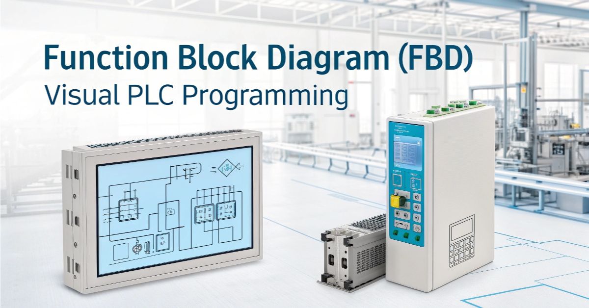

Function Block Diagram (FBD) establishes a programming approach for PLCs by using visual blocks as an alternative to conventional programming code. Blocks in Function Block Diagram correspond to various functions that function through visual connections between the block elements. Visual programming through FBD allows complex ideas to become easier to follow due to immediate overview of the operational process.
Automation and process control depend heavily on FBD according to my perspective. The programming language exists in multiple industrial facilities from production facilities to power generation sites to water purification facilities. Engineers depend on FBD for maintaining efficient safe and continual machine operation. FBD serves as a reliable solution which manufacturing companies depend on for crucial missions.
Visual programming through FBD enables rapid operation due to its speed benefits. Operating through FBD enables staff to construct systems along with performing testing and debugging at speedier rates. The visibility of logic codes through FBD generates two key benefits: a decrease of errors and faster operational speed. The use of PLCs becomes simpler for every user who operates them.
Introduction to Function Block Diagram (FBD)
PLCs receive their programming instructions through the visual Function Block Diagram (FBD). PLC programs use blocks as functional representations that include timers along with counters and logic gates. The visual connection between blocks with lines illustrates how the PLC system operations should function. The representation style of FBD makes control system design and understanding more accessible. Any system implemented with clear sequential logic starting from one block and moving to the next block benefits from FBD as a programming language.
The main differentiating factor of FBD distinguishes it from standard PLC language methods. The visual appearance of FBD remains distinct from ladder logic because its structure resembles designing flowcharts instead of viewing electrical diagrams. Structured Text requires users to code using words together with symbols for their programming needs. FBD offers beginners an advantageous learning experience which makes it simpler to understand while also providing less anxiety during instruction. As a result this language delivers a straightforward representation of the full manufacturing process from start to finish.
Core Components of FBD

Each PLC task becomes a block which Function Block Diagram displays using structured blocks and their dataflow relations through lines. Each data route between blocks appears as connecting lines in this diagram structure. All data entries occur on one side of each block while all data exits on its opposite side. The arrangement of blocks in the setup helps to explain data movement through logical systems. The diagram reveals clear connections between every successive action.
Function Block Diagram includes basic functions for logical processing which includes AND, OR and NOT operations. Control PLC systems use decision-making blocks to function properly. Each automation system in FBD requires timers together with counters to control durations or repeated performance operations. The combination of tools strengthens FBD as it enables users to tackle straightforward and complicated automation work.
Advantages of Visual PLC Programming with FBD
The simplicity of FBD’s design makes it so that anyone can easily understand the platform because of the lack of complicated code requirements. Operating staff comprising engineers and technicians can create PLC system connections through a block-based interface without issuing lines of code. Integration through visual flowcharts reduces the time required to create automation systems accordingly. The system both decreases training duration and enhances team members’ sense of confidence while they work.
The graphical nature of visual logic tools enables team members to improve their PLC system design and easily locate problems. A simple look at the block organization enables observers to find inaccuracies as soon as possible. Both changes prove simpler to accomplish and the arrangement functions to show the entire workflow connection.
Key benefits include:
- Clear, visual layout of control logic
- Faster debugging and error detection
- Easier updates and modifications
- Great for teamwork and collaboration
- Less chance of coding mistakes
Common Industrial Applications of FBD

The real world uses FBD as a standard control method for automation implementations. Through its operation FBD regulates motors and conveyor belts and mixing tanks and additional equipment. The manufacturing environment employs FBD to operate equipment alongside the monitoring of sensors as well as the management of production lines. The system shows great potential for use in food processing together with packaging and water treatment since these sectors require high precision and accurate timing.
Academic authors state FBD enables individuals to make complex machine logic appear easy and straightforward. The user interface allows program development through block connections which replace lengthy coding. The graphic layout enables users to divide essential systems such as factories and stations into smaller operational zones. The design process becomes both faster and error-free when using FBD for designing and PLC system upgrading purposes.
Here’s a quick look at how FBD fits into common uses:
| Application | How FBD Helps |
| Motor Control | Easy start/stop logic with safety interlocks |
| Conveyor Systems | Control of visual sequence and management of playback speed. |
| Process Automation | Easily keeping rhythm and continuity with the help of timers/counters. |
| HVAC Systems | Clear temperature and fan logic blocks |
| Water Treatment Plants | Reliable sensor-based flow and level control |
Best Practices for Creating Effective FBD Programs
Your FBD PLC program must begin with an organized layout. Designing FBD programs requires that large assignments should be broken up into independent modules to achieve modularity. Strong labeling practices represent a mandatory requirement because they aid recognition of your work by others. Descriptive blocks enable time efficiency as well as logical consistency in projects across different programs.
Better quality control in your programs requires testing and validation of the entire system. Simulation resources enable discovering machine problems in advance of actual operations. Documents acting as detailed descriptions of the program prove as essential because they enable secure updates and simplified maintenance.
5 basic block diagram examples for beginners in the PLC (Programmable Logic Controller) field:
1. Start/Stop Motor Control (Latching Circuit)
[Start Button] —-+
|
v
[OR Block] —-> [Motor Coil] —–> Motor Runs
^
|
[Motor Status] <—+
|
[Stop Button] —> [NOT Block] (Stop disables the circuit)
Explanation:
- Pressing Start OR Motor already ON keeps the motor running.
- Stop breaks the loop.
2. Push Button Light Control (Momentary)
[Push Button] —–> [Light Coil] —–> Light ON while pressed
Explanation:
- Simple ON/OFF control. Light is ON only while the button is pressed.
3. Fan Delayed Start (TON Timer)
[Start Button] —–> [TON Timer (5s)] —–> [Fan Coil] —–> Fan
Explanation:
- After the Start Button is pressed, the fan turns ON after 5 seconds.
4. Blinking Light (TON + NOT)
[Power ON] —–> [TON Timer 1s] —–> [NOT Block] —–> [TON Timer Loop]
TON.Q Output —–> [Light Coil] —–> Light blinks ON/OFF
Explanation:
- Timer output is inverted and fed back to the input → creates a blinking loop.
5. Box Counting with Output at 10
[Sensor] —–> [Counter] —–> [Compare: Count ≥ 10] —–> [Light]
Explanation:
- Every sensor pulse increments the counter.
When count reaches 10, the light turns ON.
Future Trends and Integration with Modern Systems
The integration of FBD happens with modern technology trends such as Industry 4.0 and IoT. The real-time data sharing capabilities of machines are now managed through visual logic implementations provided by FBD. Technical systems interact effectively in smart factories through the use of FBD. The system helps remote monitoring functions along with cloud integration and predictive maintenance capabilities.
Software tools geared towards FBD development will become both smarter and more versatile during future developments. The support for cross-platform development and mobile programming will improve according to my prediction. Users will see quicker software updates, including advanced drag-and-drop tools and artificial intelligence recommendations. FBD will evolve to simplify automation processes and create interconnected systems because of growing system complexity.
FAQ’s
How does a Function Block Diagram (FBD) work in a PLC program?
PLC systems use FBD as a visual programming language which allows users to create logic through function-based blocks to design and understand control systems more effectively.
How does FBD differ from other PLC programming languages?
FBD delivers better intuitive programming capabilities through its graphical block connections than ladder logic or structured text does when handling complex processes.
What are the benefits of using FBD in industrial automation?
FBD helps designers create simpler systems which guarantees improved readability and maintains lower rates of errors in troubleshooting and maintenance tasks particularly with complex visual processes.
Conclusion
PLC programming contains structured text which represents its most effective tool. Engineers together with technicians and professionals who work with automation should find structured text as their optimal programming solution. The structured format provides a clear understanding of complex systems through its logical structure even when you do not want to engage with complex code. Current industrial applications heavily depend on this tool because of its effectiveness.
Technology PLC progress will increase the usefulness of FBD in the future. The technology has all the needed tools alongside smart systems that integrate well and are prepared for upcoming developments. FBD maintains a clear structure for constructing small control systems as well as complete factory control systems while operating with high speed and dependability.