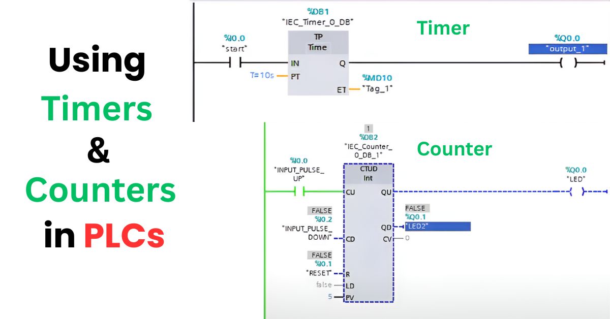
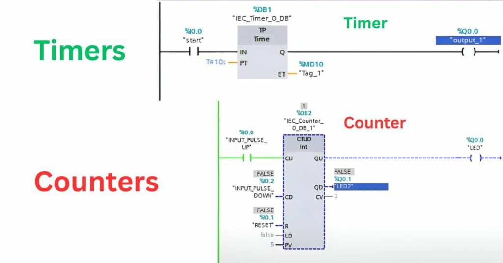
The heartbeat function of any automated system exists in PLC timers and counters. Role of timers is to measure delayed events, while counters play a significant role in calculating the frequency that certain events occur. Programmable logic controllers (PLCs) use timers and counters as an inbuilt component to enable machines to carry out specified work at fixed time intervals.
Players along with counters inside an organized PLC program control both action timing and periodic events. The timing logic in automation delivers the authentic intelligence which makes it function successfully.
The tools provide essential components that enable automation to reach improved accuracy together with faster operation and adaptable functionality. Engineers who utilize timers and counters possess the capacity to adjust every time point during a process. Smart systems achieve high efficiency together with maximum control through proper execution timing.
Introduction to PLCs and Their Core Functions
The application of PLCs (Programmable Logic Controllers) serves as the key technology for industrial automation. The operational speed and precision of machines and system monitoring and management tasks belong to PLCs. According to my perspective PLCs function as intellectual controllers in most contemporary industrial plants. The automation processes in packaging sorting and assembly functions from PLCs manage everything in a smooth manner.
Timers and counters are at the core of a PLC, and they are basic tools. Such devices help manage operations that follow time-based schedules as well as those which respond to trigger events. Counting sequences and time intervals trigger plugs that provide power to automated machines. The operation of machines becomes imprecise and their rhythm and control functions deteriorate when timers and counters are not in use.
What Are Timers in PLC Programming?
In PLC programming delays and time measurements are performed using timers. Operation timing is controlled by timers. According to my perspective timers constitute one of the essential elements for achieving smooth timed operations. The application range of timers extends to using them to delay motor operations while they activate lights through timed duration control.
Multiple timer systems exist with their own operating characteristics. Timers belong to two categories depending on whether they begin an operation with a pre-programmed waiting period or suspend an operation at a specific time. Setting up a grasp of timer operation systems enables better control over your workflow according to my understanding. Quality timing control functions are necessary for operations requiring precise measurement durations.
Common Timer Types in PLCs:
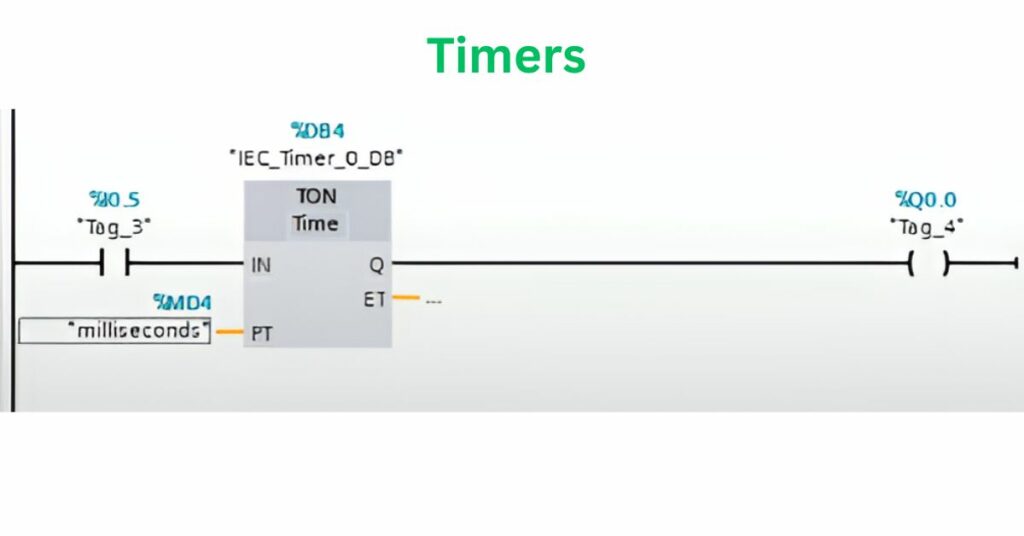
- TON (Timer ON Delay)
- TOF (Timer OFF Delay)
- RTO (Retentive Timer ON)
1. TON – Timer ON Delay
When the input is ON, this function turns on the output after a preset delay.
🪜 Ladder Logic:
| Input |—[ TON Timer T1 5s ]—| Output |
Description:
- Input is a switch (e.g., Start button).
- When the input turns ON, timer starts counting.
- After 5 seconds, the output turns ON.
Example:
|—-[ ]—-[TON T1, 5s]—-( )—-|
| I:1/0 Delay 5 sec O:2/0 |
When I:1/0 is turned ON, O:2/0 turns ON after 5 seconds.
2. TOF – Timer OFF Delay
Use: Turns OFF an output after a preset time delay once the input is turned OFF.
🪜 Ladder Logic:
| Input |—[ TOF Timer T2 5s ]—| Output |
Description:
- Output turns ON immediately with the input.
- When input turns OFF, timer starts counting down.
- Output stays ON for 5 seconds, then turns OFF.
Example:
|—-[ ]—-[TOF T2, 5s]—-( )—-|
| I:1/1 Delay OFF O:2/1 |
When I:1/1 turns OFF, O:2/1 stays ON for 5 more seconds.
3. RTO – Retentive Timer ON
Use: Accumulates time even if input goes OFF, until reset.
🪜 Ladder Logic:
| Input |—[ RTO Timer T3 5s ]—| Output |
| Reset |—[ ]—————-[RES T3] |
Description:
- Timer counts when input is ON.
- If input turns OFF, it remembers elapsed time.
- Reset input clears the timer.
Example:
|—-[ ]—-[RTO T3, 5s]———-|
| I:1/2 Accumulate |
|—-[ ]—-[RES T3]————-|
| I:1/3 Reset Timer |
Exploring PLC Counters and Their Roles
Machine counters operate by incrementing or decrementing values through monitored input signals. These devices act as counting tools for measuring different aspects of industrial procedures including part totality and cycle performance. Counters represent the best solution for monitoring repeated tasks. These systems maintain operational focus by preventing any tasks from being omitted between stages.
Different kinds of counters exist to fulfill specific operational needs in a system. The counting devices operate in three modes according to their function: upward increment, downward decrement or a combination of both methods. Understanding the correct counter selection leads to processes which both maximize their intelligence and operational effectiveness. Counter types represent basic automation tools which provide strong functionality.
Common PLC Counters:
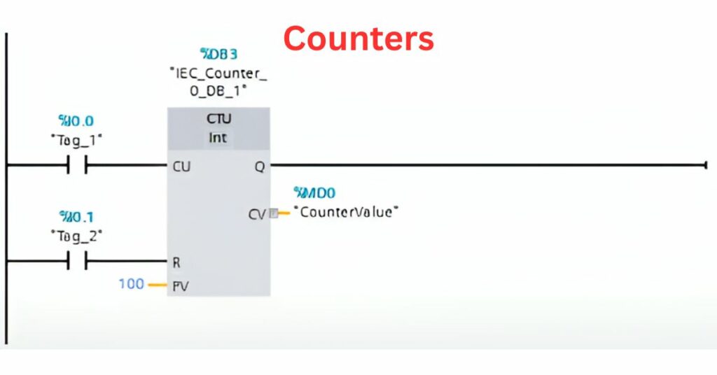
- CTU – Count Up
- CTD – Count Down
- RES – Counter Reset
These are commonly used in Allen-Bradley (RSLogix 500/Studio 5000), Siemens, and other PLC platforms, though syntax may vary slightly.
1. CTU – Count Up
Use: Increments the counter value each time the input goes from OFF to ON (rising edge).
Output (Done Bit) turns ON when the preset count is reached.
Example Logic:
|—-[ ]—-[CTU C5:0, Preset:5]—-|
| I:1/0 Counter UP |
|—-[C5:0/DN]—————-( )—|
| Output: O:2/0 |
Description:
- Each time I:1/0 (e.g., a sensor or push button) is triggered, the counter increments.
- When the count reaches 5, the done bit C5:0/DN turns ON and energizes output O:2/0.
2. CTD – Count Down
When the input is triggered, it decreases the counter value.
Example Logic:
|—-[ ]—-[CTD C5:1, Preset:5]—-|
| I:1/1 Counter DOWN |
|—-[C5:1/DN]—————-( )—|
| Output: O:2/1 |
Description:
- C5:1 starts with a preset value (e.g., 5).
- Each trigger of I:1/1 decreases the count.
- When count = 0, the done bit (C5:1/DN) turns ON.
3. RES – Counter Reset
Use: Resets a CTU or CTD counter to 0.
Example Logic:
|—-[ ]—-[RES C5:0]————-|
| I:1/2 Reset CTU Counter |
|—-[ ]—-[RES C5:1]————-|
| I:1/3 Reset CTD Counter |
Description:
- When I:1/2 is triggered, it resets counter C5:0 (Count Up) back to 0.
- When I:1/3 is triggered, it resets C5:1 (Count Down) to its preset.
Practical Applications of Timers and Counters
Engineering timers facilitate the operation of motor delays as well as lamp blinking and safety interlock systems. The length of time a device operates or remains inactive depends on timers. Machines receive their rhythm and structure titles through timers. A timer functions to delay conveyor motor starts as well as produce warning light flashing operations according to established intervals. The installation of timers creates systems which become more predictable as well as safer for users.
In both production line item counting and batch control systems counters function as the primary counting mechanism. The detection system counts the quantity of moving objects through a sensor or tracks the number of objects that finish their duties. Quality control together with operational efficiency depend on this type of system. The machine can operate until it finishes creating the specified number of products while also producing alerts to indicate threshold values.
Here’s a quick look:
| Application | Tool Used | Purpose |
| Motor Start Delay | Timer | Delay motor to avoid power surge |
| Blinking Indicator Lamp | Timer | Create on/off flashing pattern |
| Item Count on Conveyor | Counter | Track product flow on the line |
| Batch Completion Check | Counter | Stop process after fixed item count |
Programming Best Practices for Timers and Counters
Keep your labels simple, and join them with comments to enhance code cleanness. Carefully-designed labels explain to readers what each timer or counter does. The practice of proper naming conventions and comments helps staff spend less time when maintaining or troubleshooting programs. Comments that stay brief are useful as visual explanations which help team members track the flow of logic.
Maintaining separate sets of logic will stop both errors from occurring and unexpected system behavior from developing. When timer and counter outputs are combined randomly throughout the program structure becomes difficult to understand. Keeping logical systems both neat and orderly represents a more intelligent strategy. Program testing should be performed step by step on minimal sections to identify issues promptly while confirming total operational reliability.
Enhancing Automation with Timers and Counters
Timers together with counters enhance the precision and reliability while increasing flexibility in PLC systems. PLCs operate more effectively by responding quickly during critical times in addition to maintaining steady sequence execution. Automated systems achieve their smart operational status because of this advanced level of control. Accurate timing along with proper counting makes it possible for complex tasks to become as smooth and dependable as simpler operations.
Improving control system performance through mastery of these tools gives engineers the capability to develop better intelligent and efficient systems. Engineers acquire the ability to construct adaptive machines through this tool which enables both responsive operation and performance optimization. Automation growth depends on timers and counters to develop safer and faster and improved systems.
FAQ’s
What are Timers and Counters in a PLC program?
Timers and Counters are functions used to manage time-based actions and count events, crucial for automating industrial processes in PLC systems.
How do timers differ from counters in PLCs?
The duration between events or delay measurement function belongs to timers but counters operate by counting specific input occurrences.
Can timers and counters be used together in a program?
The application of multiple components together generates enhanced control systems that permit both delayed counting operations and timer sequence triggering through counting events.
Conclusion
Timing systems together with counting mechanisms enable automation to become smarter as well as more dependable. The controllers determine both time intervals and repetition frequencies. The complete feel of a PLC implementation requires timers and counters according to my perspective. These devices supply structure alongside established timeframes which enable the completion of tasks.
The correct application of timers and counters results in substantial changes according to my experience. Programs designed with logical structure enable these tools to develop systems which are both more secure and three times quicker and improved. Automation will continue expanding through the years yet timers and counters remain its fundamental components.